
Erosion Control & Geocells
GeoStrata™ HDPE Geocell - Cellular Confinement System
Textured, perforated HDPE cellular confinement system in five weld spacings from 330 mm to 712 mm and seven cell depths from 75 mm to 300 mm, supplied in 3 m × 11 m panels at 33 m² expanded. For slope stabilisation, load support, channel protection and retaining walls across Africa.
Overview
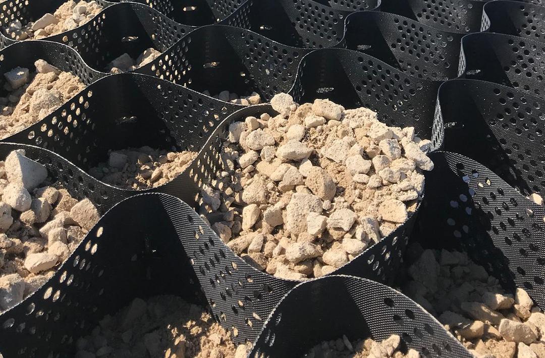
GeoStrata™ geocell is a three-dimensional cellular confinement system formed from textured, perforated polyethylene strips ultrasonically welded at fixed intervals. Collapsed for transport and expanded on site into a honeycomb structure, it confines infill laterally so that granular fill, sand or topsoil behaves as a semi-rigid mattress rather than a loose layer. The result is a substantial increase in bearing capacity and a sharp reduction in the quantity and quality of imported aggregate a project needs.
The strip carries rhomboidal indentations at a surface density of 22 to 32 per cm², developing friction between cell wall and infill and resisting downward slippage on slopes. Horizontal rows of perforations up to 10 mm in diameter, occupying less than 12 % of the cell surface, allow lateral drainage and root migration between cells while leaving confinement performance intact. Carbon black content of at least 2.0 % and environmental stress crack resistance above 5000 hours give long service life under UV exposure and sustained load.
Five weld spacings are available - 330, 356, 445, 660 and 712 mm - producing expanded cell dimensions from 244 × 210 mm to 508 × 475 mm. Each is supplied in any of seven cell depths from 75 mm to 300 mm, with minimum seam peel strength rising from 1065 N at 75 mm to 4260 N at 300 mm, tested to US ACE GL-86-19 and EN ISO 13426 Method B. Panels are produced to a 3 m × 11 m expanded format giving 33 m² per panel, larger than standard catalogue sections, which reduces panel count and site seaming over large areas. Alternative section lengths can be produced to site requirement.
Typical applications are slope and channel erosion protection, load support beneath access roads, haul roads and working platforms, gravity retaining walls and green-faced slopes, channel and riverbank lining, and reinforcement of soft subgrades where conventional aggregate depths would be uneconomic. Smaller cells and shallower depths suit topsoil retention and light surface protection; wider welds and deeper cells suit load support and heavy earth retention.
Geosynthetics Africa supplies GeoStrata geocell across South Africa and the wider continent, with delivery to more than 30 countries and installation by our own certified crews. Technical support covers cell selection, infill specification, anchoring and tendon design, with custom panel volumes delivered on a single specification and lead time.
- MaterialPolyethylene, density 0.935 - 0.965 g/cm³
- StructureTextured, perforated, ultrasonically welded honeycomb cells
- ColourBlack
- StandardTested to ASTM · GAI-LAP accredited laboratories
- Roll Width3 m expanded
- Roll Length11 m expanded · 33 m² per panel
Typical Properties
| Property | Test Method | GS HD330 | GS HD356 | GS HD445 | GS HD660 | GS HD712 |
|---|---|---|---|---|---|---|
| Weld spacing (±3 %) | - | 330 mm | 356 mm | 445 mm | 660 mm | 712 mm |
| Expanded cell width (±3 %) | - | 244 mm | 259 mm | 320 mm | 488 mm | 508 mm |
| Expanded cell length (±3 %) | - | 210 mm | 224 mm | 287 mm | 436 mm | 475 mm |
| Expanded section width (±3 %) | - | 3 m | 3 m | 3 m | 3 m | 3 m |
| Expanded section length (±3 %) | - | 11 m | 11 m | 11 m | 11 m | 11 m |
| Expanded section area (±3 %) | - | 33 m² | 33 m² | 33 m² | 33 m² | 33 m² |
| Cell depths available | - | 75–300 mm | 75–300 mm | 75–300 mm | 75–300 mm | 75–300 mm |
| Material | - | HDPE | HDPE | HDPE | HDPE | HDPE |
| Polymer density | ASTM D1505 / D792 | 0.935–0.965 g/cm³ | 0.935–0.965 g/cm³ | 0.935–0.965 g/cm³ | 0.935–0.965 g/cm³ | 0.935–0.965 g/cm³ |
| Carbon black content | ASTM D1603 / D4218 | Min. 2.0 % | Min. 2.0 % | Min. 2.0 % | Min. 2.0 % | Min. 2.0 % |
| Sheet thickness (post texturing) | ASTM D5199 | Min. 1.65 mm | Min. 1.65 mm | Min. 1.65 mm | Min. 1.65 mm | Min. 1.65 mm |
| ESCR | ASTM D1693 | >5000 hours | >5000 hours | >5000 hours | >5000 hours | >5000 hours |
| Cell wall texture | - | Rhomboidal indentations | Rhomboidal indentations | Rhomboidal indentations | Rhomboidal indentations | Rhomboidal indentations |
| Cell perforations | - | Max. 10 mm dia | Max. 10 mm dia | Max. 10 mm dia | Max. 10 mm dia | Max. 10 mm dia |
Note: The above specifications represent the product family properties. Please refer to the product datasheet for individual SKU values.
Typical Applications
View all applicationsUnpaved roads and haul road stabilisation
Base stabilisation for unpaved roads, mine haul roads, workshop yards and working platforms over weak or variable subgrades. Confinement prevents lateral spread of compacted aggregate under repeated heavy axle loading, maintaining a stable running surface without deep excavation or mass aggregate import. GS 330 and GS 356 at 100–150 mm depth.
Slope protection and erosion control
Surface protection to road embankments, mine waste dump faces, tailings dam slopes and rehabilitated cuttings. Filled with topsoil and vegetated, or with compacted aggregate, the cell structure anchors the surface layer against rainfall erosion and prevents downslope creep on gradients where loose cover will not stay in place. GS 445 and GS 660 at 100–150 mm depth.
Channel and riverbank lining
Erosion protection to lined and unlined channels, stormwater outfalls, spillway aprons and riverbanks. Perforated cell walls allow lateral drainage and pore pressure relief behind the lining, and aggregate or concrete infill resists scour at velocities that would displace loose rock. GS 445 at 150–200 mm depth.
Load support over soft subgrades
Structural layer for foundations, hardstands, laydown areas and access over soft clays, silts and fills. Confined infill behaves as a semi-rigid mattress, distributing load over a wider area and reducing the imported aggregate thickness a design would otherwise require. GS 330 and GS 356 at 150–200 mm depth.
Gravity retaining walls and steep slopes
Stacked geocell gravity walls and green-faced steep slopes as an alternative to gabions, concrete blocks or reinforced earth. Each course confines its own infill, and the outer face can be vegetated for a soft finish. Custom panel volumes on a single specification. GS 445 and GS 660 at 200–300 mm depth.
Compatible Systems
View all systemsGS 330 Series - Tight-Cell Soil Stabilisation & Unpaved Road Base
The tightest weld spacing in the range at 330 mm, giving expanded cells of 244 × 210 mm. The dense geometry maximises confinement of granular infill under repeated dynamic loading, suiting unpaved road base stabilisation, mine haul road improvement, workshop yard surfacing and light to medium load support. Cell depths 75–300 mm, 3 m × 11 m panels at 33 m² expanded.
GS 356 Series - Road Base, Pavement Stabilisation & Load Support
A 356 mm weld spacing with 259 × 224 mm expanded cells, giving versatile mid-range geometry for pavement base stabilisation, access road construction and foundation base improvement over weak or variable subgrades. Confines efficiently across a wide range of aggregate sizes. Cell depths 75–300 mm, 3 m × 11 m panels at 33 m² expanded.
GS 445 Series - Slope Protection, Erosion Control & Channel Lining
A 445 mm weld spacing with 320 × 287 mm expanded cells. The larger cell accepts topsoil, vegetated infill and coarser granular material, making it the standard choice for slope erosion protection, channel and riverbank lining, and green-faced embankments. Perforated walls allow lateral drainage and root migration between cells. Cell depths 75–300 mm, 3 m × 11 m panels at 33 m² expanded.
GS 660 Series - Large-Cell Slope & Embankment Protection
A 660 mm weld spacing with 488 × 436 mm expanded cells, covering area faster with fewer welds for large-scale slope protection, embankment facing, landfill capping and reservoir batters. Best suited to vegetated or coarse granular infill where confinement demand is moderate and coverage rate governs cost. Cell depths 75–300 mm, 3 m × 11 m panels at 33 m² expanded.
GS 712 Series - Maximum-Coverage Surface Protection
The widest weld spacing at 712 mm, with 508 × 475 mm expanded cells. Designed for maximum area coverage per panel in topsoil retention, landscaping, light surface protection and large vegetated slopes where the primary duty is holding infill in place rather than carrying load. Cell depths 75–300 mm, 3 m × 11 m panels at 33 m² expanded.
Installation Guidance
Standard Method Statement
Subgrade Preparation - Strip and trim the formation to the required level and remove all organic material, loose debris, and soft spots. Proof-roll the subgrade and cut out any weak areas before geocell installation. Place a 150-200 g/m2 non-woven geotextile separation layer over the prepared subgrade on all road base and load-bearing applications to prevent fines migration into the geocell infill layer under dynamic loading.
Panel Deployment - Unfold GeoStrata panels from the collapsed transport configuration and expand to full working dimensions by pulling from opposite corners until the panel reaches 3m x 11m. Work systematically across the site, connecting adjacent panels using the supplied connection pins or clips at all seam points before any infill is placed. Never infill a panel before its neighbours are connected - unconnected edges displace under compaction loading.
Boundary Anchorage - At all free edges, slope crests, toe trenches, and channel banks, drive steel anchor pins through the cell walls at maximum 1m centres at an angle into the subgrade. On slopes, anchor the upslope edge of each panel row before infilling using anchor pins at 500mm centres. On retaining wall applications, connect tendon straps to anchor pins at the crest as specified by the wall designer. Boundary anchorage is non-negotiable - unanchored panel edges are the primary cause of geocell installation failure.
Direction of Installation on Slopes - Install panels working from the toe of the slope upward. Each upper panel row overlaps the lower by a minimum of one full cell. Connect all seams between rows with pins at maximum 500mm centres. Use tendon straps anchored at the slope crest to prevent downslope creep of the geocell layer under sustained gravity load on slopes steeper than 1:2.
Infilling and Compaction - Fill cells with the specified infill material to 25-50mm proud of the cell top to allow for compaction settlement. Compact using a vibrating plate compactor working parallel to the slope gradient - never perpendicular. Do not allow compaction plant to operate on unfilled or partially filled cells. For vegetated applications, overfill by 10-15mm above the cell top with topsoil to allow for settlement and root establishment after vegetation cover is achieved.
Channel and Hydraulic Applications - Install panels working from the downstream end upstream so that each upper panel overlaps the lower in the direction of flow. Peg at maximum 750mm centres throughout the channel base and banks to resist hydraulic drag under peak flow conditions. For concrete-filled channel lining, place and strike the concrete within the geocell cells before adjacent panels are infilled to prevent cell displacement during pour.
Quality Assurance & Testing
Field QA/QC Checklist
- Delivery & Storage: Materials checked against the delivery note and conformance certificates, stored off the ground, covered from UV and kept clear of sharp objects and fuel.
- Material Conformance: Certificates checked for cell depth, wall thickness and seam peel strength (ISO 13426-1).
- Expansion & Anchoring: Sections fully expanded to the specified cell size and anchored at the top of slope and at the pin spacing in the design.
- Section Connections: Adjacent sections stapled or connected to the manufacturer's detail.
- Infill: Infill (soil, aggregate or concrete) placed from the top of slope down and slightly overfilled before compaction.
Manufacturing Standards
- ISO 13426-1 strength of geocell junctions
- Manufacturer installation guide
- Manufacturer QC certificates per roll
- Tested to ASTM · GAI-LAP accredited laboratories
Documents
Product Selection Guide
Compare performance properties across the entire category hierarchy before specifying.
Installation & Method Statement
Standard deployment procedures, installation specifications, and field application method statements.
QA/QC Site Checklist
Field quality control procedures, inspection checklists, and testing standards to verify installation integrity.
Technical Data Sheet (TDS)
Guaranteed minimum average roll values (MARV) and material testing properties.
Chemical Resistance / Accessories Guide
Chemical compatibility matrix and list of auxiliary materials needed for installation.
Projects Using GeoStrata™ HDPE Geocell - Cellular Confinement System
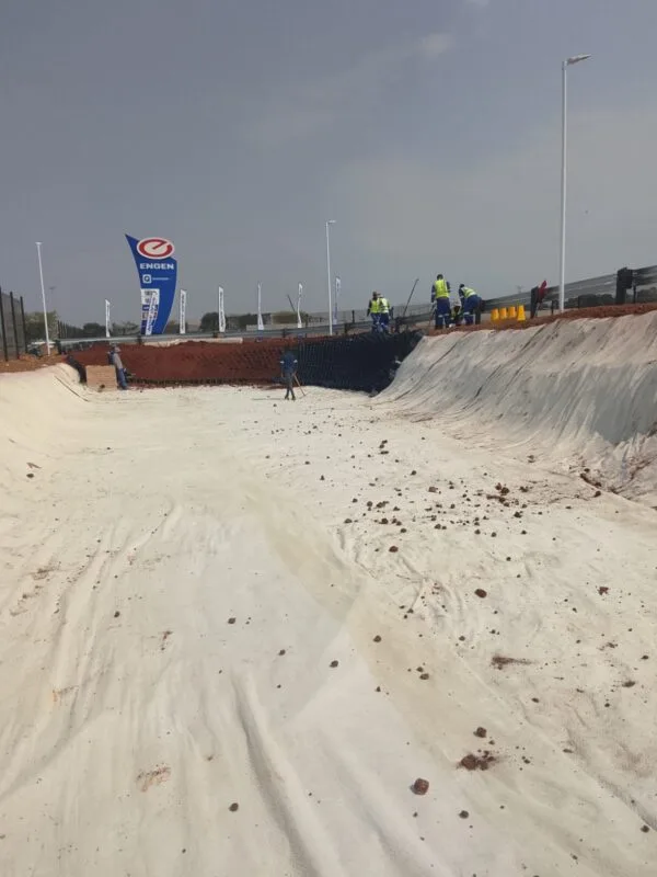
Supply and installation of an EB4000 geosynthetic clay liner and GS150 geocell system for a 1,300 m² stormwater attenuation pond at a fuel-depot expansion in South Africa.
Submit your BOQ.
Get a quote – not just a price.
Upload your BOQ or speak to our technical team for expert recommendations and support.