
Geogrids & Interlayers
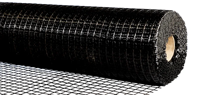
Self-Adhesive Glass Fibre Geogrid Range
Self-adhesive glass fibre geogrid from 50 to 200 kN/m for asphalt reinforcement, supplied and installed on highways, airfields and mine roads across Africa.
Overview
Self-adhesive glass fibre geogrid is engineered to control reflective cracking in asphalt overlays. Glass filaments with a Young's modulus of 81 GPa reach their full strength at around 2% elongation, so the grid picks up load almost immediately as cracks begin to open beneath the overlay, rather than after the pavement has already deformed. The polymer-modified coating protects the filaments during laying and compaction.
Grades run from 50/50 to 100/200 kN/m, covering resurfacing on secondary roads through to airfield pavements, heavily trafficked highways, bridge deck overlays and mine haul road surfacing. All grades comply with EN 15381, the European standard for geosynthetics in pavements and asphalt overlays, and carry CE marking.
The pressure-sensitive adhesive backing bonds on contact, activated by pressure from a roller or broom during laying, so there is no nailing or stapling into the existing pavement and no waiting for a separate bonding layer to grip. On a live road this shortens the window between tack coat and paver.
Rolls are 1.5 m wide as standard and can be supplied up to 3 m, with lengths from 70 m to 150 m depending on grade. We hold stock in Johannesburg and deliver to more than 30 African countries, with mill certificates supplied against every consignment.
Geosynthetics Africa supplies the range as material only or as an installed scope by our own IAGI-aligned crews, including on-site adhesion testing before paving begins and technical support from grade selection through to final sign-off.
- MaterialGlass fibre with polymer-modified coating
- StructureSelf-adhesive grid, 12.5 × 12.5 mm to 25 × 25 mm apertures
- ColourBlack
- StandardEN 15381 · CE marked · ISO 9001:2015
- Roll Width1.5 m standard (up to 3.0 m on request
- Roll Length70 m, 100 m or 150 m by grade
Typical Properties
| Property | Test Method | GFG 50/50 | GFG 100/100 | GFG 100/200 |
|---|---|---|---|---|
| Tensile strength MD × CD (guaranteed min.) | ASTM D6637 | 50 × 50 kN/m | 100 × 100 kN/m | 100 × 200 kN/m |
| Tensile strength MD × CD (nominal) | ASTM D6637 | 55 × 55 kN/m | 115 × 115 kN/m | 115 × 215 kN/m |
| Elongation at ultimate | ASTM D6637 | 2.0 ± 1% | 2.0 ± 1% | 2.0 ± 1% |
| Tensile resistance @ 2% strain | ASTM D6637 | 46 × 46 ± 10 kN/m | 95 × 95 ± 20 kN/m | 95 × 180 ± 20 kN/m |
| Young's Modulus | - | 81 GPa | 81 GPa | 81 GPa |
| Mass per unit area - plain | ASTM D5261 | ≥ 200 g/m² | ≥ 410 g/m² | ≥ 620 g/m² |
| Mass per unit area - self-adhesive | ASTM D5261 | ≥ 210 g/m² | ≥ 430 g/m² | ≥ 640 g/m² |
| Aperture (centre to centre) | - | 25 × 25 mm | 12.5 × 12.5 mm or 25 × 25 mm | 12.5 × 12.5 mm or 25 × 19 mm |
| Melting point - coating | ASTM D276 | ≥ 232 °C | ≥ 232 °C | ≥ 232 °C |
| Melting point - glass | ASTM C338 | ≥ 820 °C | ≥ 820 °C | ≥ 820 °C |
| Roll length | - | 150 m | 100 m | 70 m |
| Roll width - plain | - | 1.0 - 4.0 m | 1.0 -4.0 m | 1.0 - 4.0 m |
| Roll width - self-adhesive | - | 1.5 m std, to 3.0 m | 1.5 m std, to 3.0 m | 1.5 m std, to 3.0 m |
| Certification | EN 15381 | cE | CE | CE |
Note: The above specifications represent the product family properties. Please refer to the product datasheet for individual SKU values.
Typical Applications
View all applicationsAsphalt Overlays & Resurfacing
Controls reflective cracking when a new wearing course is laid over a cracked existing pavement.
Road Rehabilitation
Extends the life of fatigued highways and provincial roads without full-depth reconstruction.
Bridge Deck Overlays
Reinforces thin surfacing over concrete decks, where joints and shrinkage cracks reflect through quickly.
Airfield Pavements
Runway, taxiway and apron overlays carrying concentrated wheel loads and requiring long maintenance intervals.
Mine Haul Road Surfacing
Surfaced haul roads and plant access roads under heavy, repetitive axle loads.
Compatible Systems
View all systemsGlass Fibre Geogrid 50/50 kN/m
The starting grade, and the right one for most municipal and provincial resurfacing. Specify it where the existing pavement is structurally sound and the problem is thermal or block cracking working up through a new wearing course, rather than load-related fatigue. Its open apertures key well into conventional continuously graded mixes, and it is the easiest grade to place by hand on narrow carriageways, cul-de-sacs and parking areas where a lay-down frame will not fit. It also comes on the longest rolls in the range, which means fewer roll changes and fewer transverse joints on a long, uninterrupted stretch. Over-specifying above this grade on light traffic adds cost without adding pavement life.
Glass Fibre Geogrid 100/100 kN/m
The default for national routes and urban arterials, and the grade to move up to once the cracking is load-related rather than thermal. Equal strength in both directions suits the usual case where crack patterns are irregular or a full-width overlay is going down over a fatigued surface. This is the grade where the aperture choice starts to matter: the finer 12.5 mm option gives more contact area and suits thinner overlays and finer mixes, while 25 mm keys better into coarser, larger-aggregate mixes. Ask about mix design before ordering, because the aperture cannot be changed once the roll is on site.
Glass Fibre Geogrid 100/200 kN/m
Specify this where failure would be expensive to fix rather than simply where traffic is heaviest - airfield pavements that cannot be closed for rework, bridge deck overlays where joints reflect through fast, and haul roads carrying concentrated axle loads. Its extra strength runs across the roll rather than along it, so it earns its cost where cracking follows the line of the carriageway: widening joints, longitudinal construction joints and edge failures. Align the roll so that cross-direction strength runs across the crack. The heavier grid comes on shorter rolls, so allow for more roll changes and confirm handling arrangements before delivery.
Installation Guidance
Standard Method Statement
GFG installation is a pre-overlay operation. Four things determine whether it performs: surface preparation, tack coat rate, tension during placement, and keeping traffic off the grid before the overlay is laid. Both plain and self-adhesive grades require a hot bitumen tack coat. On self-adhesive grades the pressure-sensitive backing holds the grid in position while that bond develops, it does not replace it.
Store rolls between -30 and 80 degrees C at a maximum relative humidity of 85%, on a dry flat surface, preferably under cover. Self-adhesive rolls must be stored standing vertically upright, not laid flat. Rolls kept outdoors must be covered with proper waterproof covering.
Prepare the existing pavement surface. It must be clean, dry and free of dust, dirt, loose material, standing water and contamination. Do not place grid on a surface that is wet or contaminated with oil, soil or excessive dust.
Check surface temperature before starting. The road surface must be between 5 and 60 degrees C. On a paved surface less than 24 hours old, between 5 and 46 degrees C.
Seal all cracks wider than 6 mm with an approved sealant or the appropriate levelling course mix. Repair potholes, failed and cracked sections as instructed by the engineer. The surface must be level enough for the grid to make solid contact with the base course.
Apply a hot bitumen tack coat at a residual rate of 0.25 to 0.35 kg/m2 for plain grades, or 0.40 to 0.60 kg/m2 for self-adhesive grades. The rate varies with existing surface condition and ambient temperature. The tack coat must extend 75 mm beyond the grid on all sides. Tack coat and grid must be applied by trained personnel.
Confirm roll orientation against the design drawings before unrolling. Self-adhesive grades are laid adhesive face down. GFG 100/200 is asymmetric, with its higher strength in the cross direction, so its orientation must follow the design engineer's direction of principal stress.
Fasten the leading edge firmly to the road, then unroll in the direction of paving. Maintain tension from the end of the roll continuously until the remaining grid is fastened down. Placement may be mechanical, using a purpose-built laydown frame, hydraulically controlled device or modified tractor, or manual on smaller and awkward sections.
Brush the laid grid down vigorously with a stiff broom, or roll it with a rubber-coated drum roller or pneumatic tyre roller, to achieve full bond. Apply vegetable oil to pneumatic tyre roller tyres to stop the grid lifting during rolling.
Overlap transverse joints by 75 to 150 mm in the direction of the paver, and longitudinal joints by 25 to 50 mm. Tack thoroughly at all joints and overlaps. Use shortened lengths through curves. Where nails are specified, size them to the sub-surface thickness and use washers larger than the grid aperture.
Stop the grid 100 to 150 mm short of the pavement edge to prevent capillary water ingress.
Remove all wrinkles and wrap-ins before paving. Sufficient tension during placement is how they are avoided. To remove one, cut through the middle of the wrinkle and fasten the repair area down firmly to eliminate lifting or movement.
On self-adhesive grades, verify the bond before paving. Insert the hook of a calibrated spring balance into the centre of a representative installed section and pull vertically upward until four to five apertures lift on all sides, recording the force. A reading of 9 kg or more means it is safe to pave. Below 9 kg, stop and establish the cause, usually water or debris contamination, before continuing.
Keep traffic off the exposed grid. Where unavoidable, keep it below 10 km/h with no sudden stopping or starting, and keep static front-wheel turning to an absolute minimum. Any section damaged by construction traffic must be removed and patched before paving. To protect the grid from displacement by loaded asphalt trucks, apply a light cover of 8 to 12 mm stone chips or a thin asphalt mix layer.
Pave only once the tack coat is fully cured and the grid is firmly and uniformly bonded. Place hot mix asphalt directly over the grid, feeding mix under the paver with a shovel to prevent displacement. The polymer-modified coating, stable to at least 232 degrees C, remains intact through standard paving temperatures. Do not use plant with damaged, worn or broken tyres. Compact the overlay to the contract specification. Personnel handling glass fibre grid must wear protective clothing, gloves and safety glasses.
Quality Assurance & Testing
Field QA/QC Checklist
- Delivery & Storage: Materials checked against the delivery note and conformance certificates, stored off the ground, covered from UV and kept clear of sharp objects and fuel.
- Surface Preparation: Existing surface cleaned, cracks sealed and potholes repaired; surface dry before laying.
- Tack Coat: Bitumen tack coat applied at the rate set for the product (ASTM D6140 asphalt retention for paving fabrics) and evenly spread.
- Placement: Interlayer laid without wrinkles; overlaps and transverse joints to the manufacturer's guide; folds cut and lapped.
- Overlay: Asphalt overlay placed at the specified minimum thickness and temperature; no sharp turning of plant on the interlayer.
Manufacturing Standards
- ASTM D6140 asphalt retention (paving fabrics)
- ISO 10319 tensile strength (grids)
- Manufacturer installation guide
- EN 15381 · CE marked · ISO 9001:2015
Documents
Product Selection Guide
Compare performance properties across the entire category hierarchy before specifying.
Installation & Method Statement
Standard deployment procedures, installation specifications, and field application method statements.
QA/QC Site Checklist
Field quality control procedures, inspection checklists, and testing standards to verify installation integrity.
Technical Data Sheet (TDS)
Guaranteed minimum average roll values (MARV) and material testing properties.
Chemical Resistance / Accessories Guide
Chemical compatibility matrix and list of auxiliary materials needed for installation.
Projects Using Self-Adhesive Glass Fibre Geogrid Range
Submit your BOQ.
Get a quote – not just a price.
Upload your BOQ or speak to our technical team for expert recommendations and support.