
Glass Fibre Geogrid (GFG) - Fibreglass Asphalt Reinforcement Grid for Roads, Highways & Airfields
Glass Fibre Geogrid (GFG) is a range of polymer-coated fibreglass geogrids that reinforce the asphalt layers of flexible pavements. A Young's Modulus of 81 GPa - over fifteen times stiffer than polymer geogrids - mobilises reinforcement at the very low strains at which asphalt actually cracks, so GFG intercepts reflective cracking at the base of the overlay before it reaches the surface. Six products across three strength grades, 50/50 to 100/200 kN/m, plain or self-adhesive, CE marked to EN 15381 and delivered to 30+ countries across Africa.
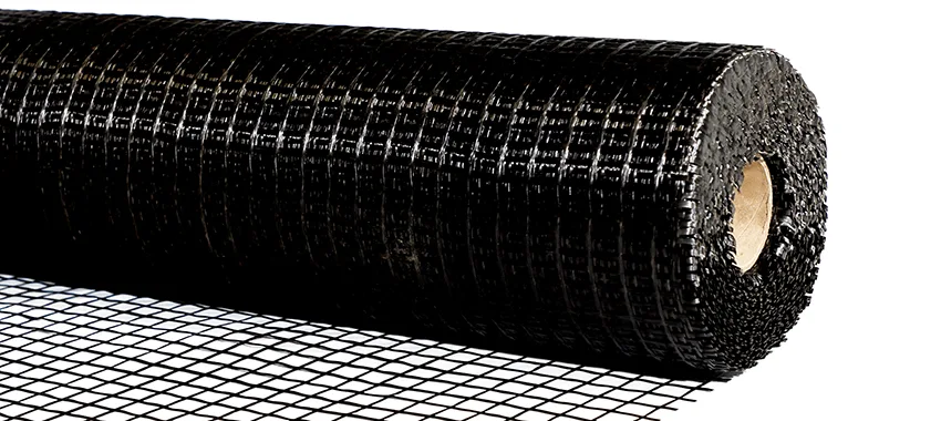
Technical Specification of Glass Fibre Geogrid (GFG) - Fibreglass Asphalt Reinforcement Grid for Roads, Highways & Airfields
Glass Fibre Geogrid (GFG) is a family of geogrids manufactured from high-grade glass fibre rovings, processed through a precisely controlled system to create a uniform reticular grid structure. Strict quality control of both raw materials and production parameters, under ISO 9001:2015 quality management, ensures consistent aperture geometry, integral junction strength and repeatable mechanical performance at very low strain.
GFG is finished with a polymer-modified coating that protects the glass strands and bonds the grid into the asphalt above. The coating is stable to a melting point of ≥232 °C and the glass itself softens only above 820 °C, so the grid holds its geometry and its strength through hot mix laydown and compaction. Every grade is available in two forms: plain, and with a pressure-sensitive self-adhesive backing for faster, more accurate placement. Both forms are bonded to the pavement with a hot bitumen tack coat.
The defining performance characteristic of GFG is its Young's Modulus of 81 GPa (81,000 MPa), derived from the inherent stiffness of glass fibre. This is significantly higher than polymer-based geogrids, which typically fall between 1,000 and 5,000 MPa. It matters because asphalt cracks at very low strains: GFG reaches 95 kN/m of tensile resistance at just 2% strain on the 100/100 grade, so it is carrying load well before the surrounding asphalt reaches its own cracking strain.
Placed at the base of an asphalt overlay, GFG intercepts the concentrated tensile stress at the tip of a crack in the underlying pavement and redistributes it horizontally across the grid. The crack still moves, but the energy driving it upward is dissipated sideways rather than propagating through to the running surface. This is the mechanism behind reflective crack control, and it is why a reinforced overlay carries traffic materially longer before the first cracks reappear.
Three strength grades are available - GFG 50/50, GFG 100/100 and GFG 100/200 - each supplied plain or self-adhesive, giving six products in total, with a choice of aperture on the two heavier grades. Together they cover the full range of overlay reinforcement requirements, from municipal resurfacing through highway rehabilitation to heavily trafficked highway and airfield pavements. All grades are CE marked and tested to EN 15381, ASTM D6637 and EN ISO 10319.
Typical Values for GEOGRIDS INTERLAYERS
Properties & Dimensions
| Property | Test Method | GFG 50/50 | GFG 100/100 | GFG 100/200 |
|---|---|---|---|---|
| Tensile strength MD × CD (guaranteed min.) | ASTM D6637 | 50 × 50 kN/m | 100 × 100 kN/m | 100 × 200 kN/m |
| Tensile strength MD × CD (nominal) | ASTM D6637 | 55 × 55 kN/m | 115 × 115 kN/m | 115 × 215 kN/m |
| Elongation at ultimate | ASTM D6637 | 2.0 ± 1% | 2.0 ± 1% | 2.0 ± 1% |
| Tensile resistance @ 2% strain | ASTM D6637 | 46 × 46 ± 10 kN/m | 95 × 95 ± 20 kN/m | 95 × 180 ± 20 kN/m |
| Young's Modulus | - | 81 GPa | 81 GPa | 81 GPa |
| Mass per unit area - plain | ASTM D5261 | ≥ 200 g/m² | ≥ 410 g/m² | ≥ 620 g/m² |
| Mass per unit area - self-adhesive | ASTM D5261 | ≥ 210 g/m² | ≥ 430 g/m² | ≥ 640 g/m² |
| Aperture (centre to centre) | - | 25 × 25 mm | 12.5 × 12.5 mm or 25 × 25 mm | 12.5 × 12.5 mm or 25 × 19 mm |
| Melting point - coating | ASTM D276 | ≥ 232 °C | ≥ 232 °C | ≥ 232 °C |
| Melting point - glass | ASTM C338 | ≥ 820 °C | ≥ 820 °C | ≥ 820 °C |
| Roll length | - | 150 m | 100 m | 70 m |
| Roll width - plain | - | 1.0 - 4.0 m | 1.0 -4.0 m | 1.0 - 4.0 m |
| Roll width - self-adhesive | - | 1.5 m std, to 3.0 m | 1.5 m std, to 3.0 m | 1.5 m std, to 3.0 m |
| Certification | EN 15381 | cE | CE | CE |
Popular Catalogue Items
Related Product Groups
Three Questions To Ask Before You Order
1.What is a glass fibre geogrid and how does it differ from a standard geogrid?
2.What is reflective cracking and how does GFG prevent it?
3.What is the difference between GFG 50/50, GFG 100/100 and GFG 100/200?
4.How is GFG installed on a road overlay project?
5.Does self-adhesive glass fibre geogrid still need a tack coat?
6.Can GFG be used on airfields and heavily trafficked roads?
7.What roll widths and lengths are available?
8.How do you check the geogrid has bonded before paving?
Specification For The Design, Installation Of Glass Fibre Geogrid (GFG) - Fibreglass Asphalt Reinforcement Grid for Roads, Highways & Airfields
GFG installation is a pre-overlay operation. Four things determine whether it performs: surface preparation, tack coat rate, tension during placement, and keeping traffic off the grid before the overlay is laid. Both plain and self-adhesive grades require a hot bitumen tack coat. On self-adhesive grades the pressure-sensitive backing holds the grid in position while that bond develops, it does not replace it.
Store rolls between -30 and 80 degrees C at a maximum relative humidity of 85%, on a dry flat surface, preferably under cover. Self-adhesive rolls must be stored standing vertically upright, not laid flat. Rolls kept outdoors must be covered with proper waterproof covering.
Prepare the existing pavement surface. It must be clean, dry and free of dust, dirt, loose material, standing water and contamination. Do not place grid on a surface that is wet or contaminated with oil, soil or excessive dust.
Check surface temperature before starting. The road surface must be between 5 and 60 degrees C. On a paved surface less than 24 hours old, between 5 and 46 degrees C.
Seal all cracks wider than 6 mm with an approved sealant or the appropriate levelling course mix. Repair potholes, failed and cracked sections as instructed by the engineer. The surface must be level enough for the grid to make solid contact with the base course.
Apply a hot bitumen tack coat at a residual rate of 0.25 to 0.35 kg/m2 for plain grades, or 0.40 to 0.60 kg/m2 for self-adhesive grades. The rate varies with existing surface condition and ambient temperature. The tack coat must extend 75 mm beyond the grid on all sides. Tack coat and grid must be applied by trained personnel.
Confirm roll orientation against the design drawings before unrolling. Self-adhesive grades are laid adhesive face down. GFG 100/200 is asymmetric, with its higher strength in the cross direction, so its orientation must follow the design engineer's direction of principal stress.
Fasten the leading edge firmly to the road, then unroll in the direction of paving. Maintain tension from the end of the roll continuously until the remaining grid is fastened down. Placement may be mechanical, using a purpose-built laydown frame, hydraulically controlled device or modified tractor, or manual on smaller and awkward sections.
Brush the laid grid down vigorously with a stiff broom, or roll it with a rubber-coated drum roller or pneumatic tyre roller, to achieve full bond. Apply vegetable oil to pneumatic tyre roller tyres to stop the grid lifting during rolling.
Overlap transverse joints by 75 to 150 mm in the direction of the paver, and longitudinal joints by 25 to 50 mm. Tack thoroughly at all joints and overlaps. Use shortened lengths through curves. Where nails are specified, size them to the sub-surface thickness and use washers larger than the grid aperture.
Stop the grid 100 to 150 mm short of the pavement edge to prevent capillary water ingress.
Remove all wrinkles and wrap-ins before paving. Sufficient tension during placement is how they are avoided. To remove one, cut through the middle of the wrinkle and fasten the repair area down firmly to eliminate lifting or movement.
On self-adhesive grades, verify the bond before paving. Insert the hook of a calibrated spring balance into the centre of a representative installed section and pull vertically upward until four to five apertures lift on all sides, recording the force. A reading of 9 kg or more means it is safe to pave. Below 9 kg, stop and establish the cause, usually water or debris contamination, before continuing.
Keep traffic off the exposed grid. Where unavoidable, keep it below 10 km/h with no sudden stopping or starting, and keep static front-wheel turning to an absolute minimum. Any section damaged by construction traffic must be removed and patched before paving. To protect the grid from displacement by loaded asphalt trucks, apply a light cover of 8 to 12 mm stone chips or a thin asphalt mix layer.
Pave only once the tack coat is fully cured and the grid is firmly and uniformly bonded. Place hot mix asphalt directly over the grid, feeding mix under the paver with a shovel to prevent displacement. The polymer-modified coating, stable to at least 232 degrees C, remains intact through standard paving temperatures. Do not use plant with damaged, worn or broken tyres. Compact the overlay to the contract specification. Personnel handling glass fibre grid must wear protective clothing, gloves and safety glasses.
Featured Projects Across Africa
Related Resources
Common GLASS ASPHALT GEOGRID Applications
Request a Quote for This Product Family
Upload your BOQ, drawings, or specifications and our technical team will provide a detailed proposal.
Have a project? Start with us.
Get expert engineering support, reliable material supply, and best-in-class installation.