
Polymeric Geostrips
TechStrap polymeric geostrips are flat webbing-structure reinforcement strips engineered for reinforced soil and mechanically stabilised earth structures. Each strap carries a core of closely packed, tensioned high-tenacity polyester filament yarn tendons encased in a linear low density polyethylene sheath, giving high pullout resistance, low creep and long-term durability in granular fill. Available from 30 to 135 kN, and used with precast panel, block and wire mesh facing systems on reinforced soil walls, shored MSE walls and bridge abutments.
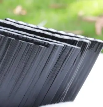
Technical Specification of Polymeric Geostrips
TechStrap polymeric geostrips are geosynthetic reinforcement strips with a flat webbing structure, engineered specifically for the reinforcement of soils and granular fills in reinforced soil and mechanically stabilised earth structures. Unlike planar geogrids and geotextiles, which reinforce across a continuous sheet, geostrips are discrete linear elements laid at designed horizontal and vertical spacings and connected
Each strap comprises a core of closely packed and tensioned high-tenacity polyester filament yarn tendons encased in a sheath of linear low density polyethylene. The polyester tendons carry the entire tensile load and are selected for high molecular weight and low carboxyl end group content, the two properties that govern long-term resistance to hydrolysis in soil. The LLDPE sheath carries no load: it protects the tendons from mechanical damage during placement and compaction, resists chemical and biological attack in the fill, and provides the surface texture that develops frictional interaction with the surrounding soil.
Strap reinforcement resists lateral earth pressure by mobilising pullout resistance along the length embedded beyond the potential failure surface. Capacity is therefore governed by two independent checks: tensile rupture of the strap, assessed against long-term design strength after reduction factors for creep, installation damage and durability; and pullout, assessed from the strap-soil interface friction, the embedded length and the confining stress at that level. Strap grade, length, and horizontal and vertical spacing are selected together against wall height, backfill properties and surcharge, so design is a layout exercise as much as a strength selection.
Principal applications are reinforced soil and MSE retaining walls, shored MSE walls supporting deep excavations, bridge abutment support systems and industrial platform foundations, across roads and highways, railways, mining and property development. TechStrap is available from 30 to 135 kN and is used with precast concrete panel, segmental block and welded wire mesh facings; on panel-faced walls the connection is made through purpose-designed panel connectors. The same strap technology forms the longitudinal elements of TechLink strip-bonded geogrids, so the two products share polyester yarn and sheath characteristics and are frequently specified on the same project, straps for the wall and grid for basal reinforcement or higher-load layers.
Typical Values for GEOGRIDS INTERLAYERS
Properties & Dimensions
| Grade | Test Method | Ultimate Tensile Strength, kN |
|---|---|---|
| TechStrap 30 | ISO 10319 / ASTM D 6637 | 30 |
| TechStrap 40 | ISO 10319 / ASTM D 6637 | 40 |
| TechStrap 50 | ISO 10319 / ASTM D 6637 | 50 |
| TechStrap 100 | ISO 10319 / ASTM D 6637 | 100 |
| TechStrap 120 | ISO 10319 / ASTM D 6637 | 120 |
| TechStrap 135 | ISO 10319 / ASTM D 6637 | 135 |
Popular Catalogue Items
Related Product Groups
Three Questions To Ask Before You Order
1.How do I choose between polymeric geostrips and geogrid reinforcement?
2.Q: Why does pullout often govern strap design rather than tensile strength?
3.Q: What backfill and site conditions do geostrips need?
Specification For The Design, Installation Of Polymeric Geostrips
Set panels and connect - Place the facing units to line and level on the levelling pad, brace to the specified batter, and connect each strap to its panel at the designed position. Mark the required strap length per the drawings and fix rear anchorage where the design calls for it. Connection capacity frequently governs on panel-faced walls, so connections are installed and inspected individually rather than assumed.
Lay straps and place fill - Lay straps flat and taut on the compacted lift, perpendicular to the facing, at the horizontal spacing shown on the drawings. Place fill by end-tipping onto material already placed and spreading forward over the straps, never tipping directly onto them. Keep plant off uncovered straps and compact in lifts to the specified density, working parallel to the facing and using lighter equipment within the zone immediately behind the panels.
Repeat and record - Repeat the cycle of backfilling, compacting, laying straps and setting the next panel course until design height, then cast the coping beam or complete the specified top detail. Record grade, length, layer level, spacing and date for each layer placed, along with any damage and its remediation. These records form the acceptance documentation and are routinely requested at handover.
Featured Projects Across Africa
Related Resources
Common POLYMERIC GEOSTRIPS Applications
Request a Quote for This Product Family
Upload your BOQ, drawings, or specifications and our technical team will provide a detailed proposal.
Have a project? Start with us.
Get expert engineering support, reliable material supply, and best-in-class installation.