
Strip Bonded Geogrids
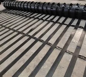
Strip-bonded geogrids are formed from parallel arrays of polymeric geostrips bonded at their cross-over junctions, each strip carrying a core of high-tenacity polyester filament yarn tendons inside a polyethylene protective sheath. Available from 100 to 1400 kN/m ultimate tensile strength, with long-term design strengths to 929 kN/m over a 120-year design life, they carry loads beyond the range of extruded and coated planar geogrids - basal reinforcement of embankments over soft ground, tall reinforced soil walls, and bridge abutments.
Technical Specification of Strip Bonded Geogrids
TechLink strip-bonded geogrids are high-performance geosynthetics engineered for soil reinforcement applications demanding high to ultra-high tensile strength. The product consists of two sets of polymeric geostrips - one set of parallel strips aligned in the longitudinal direction, another aligned in the cross-direction - bonded to each other at the cross-over junctions to form a stable grid structure. This construction differs fundamentally from extruded, punched-and-drawn or coated woven geogrids, and it is what allows the range to reach tensile strengths well beyond the practical ceiling of planar geogrid manufacture.
The longitudinal strips comprise an inner core of tensile elements consisting of high-tenacity polyester filament yarn tendons within an outer protective sheath of polyethylene. The polyester yarns are selected for high molecular weight and low carboxyl end group count, which governs long-term resistance to hydrolysis and therefore the durability reduction factor applied in design. The polyethylene sheath carries no load; its function is to protect the tendons from mechanical damage during placement and compaction, resist weathering and chemical attack, and provide frictional interaction with the surrounding fill.
Reinforcement design is governed by long-term design strength rather than ultimate tensile strength. LTDS is obtained by dividing the characteristic short-term tensile strength by reduction factors for creep rupture, installation damage and durability, following ISO/TR 20432 - the methodology also adopted by BS 8006-1, IS 17372 and IS 17373, and referenced by IRC:SP:102. For TechLink at a 120-year design life, 20°C and pH 5–9, the published factors are 1.38 for creep, 1.03 for installation damage in coarse and sandy gravels or 1.01 in silty sand, and 1.06 for durability. Applied to the grade range, this yields long-term design strengths from 66 to 929 kN/m in gravels and 68 to 948 kN/m in sands.
The range suits structures where required reinforcement strength exceeds what conventional planar geogrids can deliver, or where a high-modulus, low-creep reinforcement is needed to control deformation. Principal applications are basal reinforcement of embankments over soft or compressible ground, including piled and column-supported embankments; tall reinforced soil walls and bridge abutments; steepened reinforced soil slopes; and load transfer platforms over ground improvement elements. Cross-direction strength is nominal at 1 kN/m, so the product is designed as uniaxial reinforcement and must be laid with the machine direction aligned to the principal tensile demand.
Typical Values for GEOGRIDS INTERLAYERS
Properties & Dimensions
| Grade | UTS (MD), kN/m | LTDS Gravels, kN/m | LTDS Sands, kN/m | Roll Length, m |
|---|---|---|---|---|
| TL 100 | 100 | 66 | 68 | 200 |
| TL 200 | 200 | 133 | 135 | 200 |
| TL 300 | 300 | 199 | 203 | 200 |
| TL 400 | 400 | 265 | 271 | 130 |
| TL 500 | 500 | 332 | 338 | 100 |
| TL 600 | 600 | 398 | 406 | 100 |
| TL 700 | 700 | 465 | 474 | 50 |
| TL 800 | 800 | 531 | 541 | 50 |
| TL 900 | 900 | 597 | 609 | 50 |
| TL 1000 | 1000 | 664 | 677 | 50 |
| TL 1100 | 1100 | 730 | 745 | 50 |
| TL 1200 | 1200 | 796 | 812 | 50 |
| TL 1300 | 1300 | 863 | 880 | 50 |
| TL 1400 | 1400 | 929 | 948 | 50 |
Popular Catalogue Items
Related Product Groups
Three Questions To Ask Before You Order
1.What is a strip-bonded geogrid?
2.What is LTDS and why does it matter more than tensile strength?
3.How is long-term design strength calculated?
4.What tensile strengths are available?
5.When should I use strip-bonded geogrid instead of a planar geogrid?
6.Does it need to be laid in a particular direction?
7.What are the reduction factors?
8.How does polyester perform over a long design life?
9.What are the site handling requirements?
10.What information do you need to recommend a grade?
Specification For The Design, Installation Of Strip Bonded Geogrids
Prepare the formation level, remove sharp protrusions and any material that could damage the reinforcement, and confirm the bearing layer meets the design assumptions. Reinforcement is laid with the machine direction aligned to the principal tensile demand - perpendicular to the wall face on reinforced soil walls, and along the direction of spreading on basal reinforcement. This orientation is critical rather than preferential: cross-direction strength is nominal at 1 kN/m, so a roll laid across the wrong axis leaves the structure effectively unreinforced. Check roll orientation against the design drawings before the first lift is placed, and re-check after any change of crew or roll. Adjacent rolls are laid to the overlap or joint detail shown on the drawings; strip-bonded geogrid is not spliced by overlapping alone where load transfer across the joint is required, so follow the specified connection or bodkin detail.
Place fill by end-tipping onto previously placed material and spreading forward over the reinforcement, never by tipping directly onto it. Maintain a minimum cover thickness before any plant tracks over the reinforcement — typically 150 to 200 mm depending on fill type and plant weight — and avoid sharp turning, braking or acceleration on the first lift. Compact in lifts to the specified density using equipment appropriate to the fill. The published installation damage reduction factors of 1.03 in coarse and sandy gravels and 1.01 in silty sand were derived from full-scale field testing that simulates correct placement; departing from good practice, particularly with large angular aggregate, produces higher damage than the design assumed and erodes the strength the structure was designed for.
Cover the reinforcement within one day of placement. Weathering resistance is good and brief exposure has little effect, but the datasheet reduction factors assume prompt covering, and prolonged exposure invalidates that assumption. Where reinforcement connects to a facing system - precast concrete panels, segmental blocks, welded wire mesh or wrap-around - the connection is a designed structural element and must be installed exactly per the drawings, since connection capacity rather than reinforcement strength frequently governs. Record grade, roll number, layer level, orientation and date for each layer placed, together with any observed damage and its remediation. These records form the acceptance documentation and are routinely requested at handover on reinforced soil structures.
Featured Projects Across Africa
Related Resources
Common STRIP BONDED GEOGRIDS Applications
Request a Quote for This Product Family
Upload your BOQ, drawings, or specifications and our technical team will provide a detailed proposal.
Have a project? Start with us.
Get expert engineering support, reliable material supply, and best-in-class installation.