
Geomembrane Liners
GSE® HD Leak Location Conductive Geomembrane Liner - GRI-GM13
GRI-GM13 certified HDPE geomembrane with an integral conductive layer enabling Electrical Leak Location survey after installation - through cover soils and under water, without excavation. Specified for high-consequence TSF, hazardous waste cells and double-liner systems where post-installation leak detection is a regulatory or design requirement. 1.5mm to 2.5mm, available smooth or textured.
Overview
Find the Leak Without Digging for It
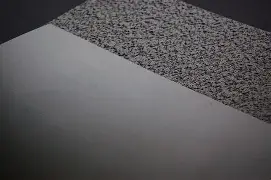
GSE Leak Location Conductive is a co-extruded HDPE geomembrane with a conductive layer on the underside. That layer turns the liner itself into part of the leak detection system: an electrical survey can locate a defect through cover soils or under water, with no excavation and no guesswork about where to look.
Why conductive, not just surveyed. Electrical leak location can be run over conventional geomembrane, but it depends on the subgrade beneath providing a return path - which means variable ground conditions produce variable results. A conductive backing gives the survey a defined conductive plane directly beneath the liner, so both spark and dipole methods work with materially higher reliability than the same survey over non-conductive sheet. Surveys get faster, cheaper and more accurate, and a pinhole anywhere on the panel is detectable.
Seaming is where conductive liners are won or lost. During fusion welding, the upper flap of one panel can contact the conductive layer of the panel below, creating electrical pathways that either break conductivity across the sheet or generate false positives over every seam. Solmax's patented Iso-wedge tool, fitted to a standard fusion welding machine, isolates the upper flap from the bottom panel during seaming and eliminates the problem. It is the difference between a conductive liner that surveys cleanly and one that produces a map of defects at every weld.
The survey. Bare surveys use the S-100 spark tester, supplied with cart, brush and seam electrodes so wrinkles, slopes and seams can all be tested. Covered surveys use the dipole method through cover soil or water. Both are supported by the same liner.
Where to specify it. High-consequence containment where a leak cannot be tolerated and cannot easily be found later — TSF base liners and double-liner systems, hazardous waste cells, landfill primary liners, and any facility where a regulator or design brief requires post-installation leak location. Also worth specifying anywhere cover soil is placed early, since that is exactly the condition that makes conventional defect-finding prohibitively expensive.
Orientation is critical. The conductive layer is on the underside. The sheet must be deployed conductive-side down, against the subgrade. A panel laid inverted will not survey.
Available in GSE HD and GSE LL grades, smooth, textured and white. Geosynthetics Africa supplies ex-stock with IAGI-aligned installation, Iso-wedge seaming and a full QA dossier under our own name.
- MaterialHigh-Density Polyethylene (HDPE) - co-extruded with conductive layer
- StructureConductive layer on underside · smooth, textured or white
- ColourBlack · white reflective option
- StandardGRI-GM13 · SANS 1526
- Roll Width7m standard
- Roll LengthGrade Dependent
Typical Properties
| Testing Properties | Test Method | Unit | 1.0mm | 1.5mm | 2.0mm | 2.5mm |
|---|---|---|---|---|---|---|
| Thickness | ASTM D5199 | mm | 1.00 | 1.50 | 2.00 | 2.50 |
| Density | ASTM D792 | g/cm³ | ≥ 0.940 | ≥ 0.940 | ≥ 0.940 | ≥ 0.940 |
| Tensile strength at break | ASTM D6693 | kN/m | 27 | 40 | 53 | 67 |
| Tensile Strength at Yield | ASTM D6693 | kN/m | 15 | 22 | 29 | 37 |
| Tear resistance | ASTM D1004 | N | 106 | 168 | 224 | 280 |
| Puncture resistance | ASTM D4833 | N | 320 | 480 | 640 | 800 |
| Stress crack resistance | ASTM D5397 | hr | ≥ 500 | ≥ 500 | ≥ 500 | ≥ 500 |
| Roll width | - | m | 7 | 7 | 7 | 7 |
| Roll Length | - | m | 210 | 150 | 110 | 85 |
| Area per roll | - | m² | 1470 | 1050 | 770 | 595 |
Note: The above specifications represent the product family properties. Please refer to the product datasheet for individual SKU values.
Typical Applications
View all applicationsTailings Storage Facility Lining
HDPE lining for tailings cells and embankments, including composite and double liner systems with leak detection.
Heap Leach Pad Lining
HDPE barriers beneath ore stacks and solution ponds for leach solution containment and recovery.
Reservoir & Dam Lining
HDPE lining to control seepage in dams, reservoirs and process water storage, selected for site conditions.
Landfill, Ash & Bund Lining
HDPE barriers for landfill cells, ash facilities and secondary containment, with protection and drainage layers as required.
Compatible Systems
View all systemsHDPE Smooth Geomembranes
The standard profile for flat and gently graded containment surfaces - TSF base liners, landfill cells, reservoirs, canals and process ponds on slopes not exceeding 3H:1V. Virgin resin, GRI-GM13 certified. 1.0 mm – 3.0 mm.
HDPE Textured Geomembranes (Single & Double)
Specified where slope stability and interface friction are design-critical. Single-textured for one-sided friction interfaces; double-textured mandatory on slopes steeper than 3H:1V. GRI-GM13 certified. 1.0 mm – 2.5 mm.
HDPE White / Reflective Geomembranes
Reflective white surface bonded to a black HDPE base - reduces liner temperature in high UV environments where exposed black HDPE can exceed 70 °C. Specified for heap leach pads, exposed caps and long-term surface applications. GRI-GM13 certified. 1.0 mm – 2.5 mm.
HDPE Conductive Geomembranes (ELL-enabled)
Conductive layer enables Electrical Leak Location (ELL) testing through cover soils and under water - pinpointing defects without excavation. Specified for high-consequence TSF, hazardous waste and double-liner systems requiring post-installation leak detection. 1.5 mm – 2.5 mm.
HDPE High-Temperature Geomembranes
Engineered for process fluid temperatures exceeding standard HDPE thermal tolerance - hot leach solutions, thermal heap leach and elevated-temperature industrial ponds above 60 °C. Project-specified. Contact our technical team for application assessment
Installation Guidance
Standard Method Statement
Installation follows the approved project method statement, panel layout and QA/QC plan. The receiving surface is inspected before deployment. Panel overlaps, anchorage, temporary restraint and welding conditions are set for the selected liner and equipment, following manufacturer guidance and the project specification.
Dual-track fusion welding and extrusion welding are used as appropriate to the seam and detail. Non-destructive testing uses the applicable method: pressurised air-channel evaluation to ASTM D5820 for dual seams, and vacuum-chamber evaluation to ASTM D5641 where suitable. Destructive peel and shear testing to ASTM D6392 is performed at the frequency and acceptance criteria defined in the approved project QA/QC plan.
Repairs are recorded and retested using the applicable method before acceptance and covering. Handover documentation is defined in the agreed scope and may include material roll records, panel layouts, weld logs, non-destructive and destructive test records, repair logs, as-built drawings and the handover certificate.
Quality Assurance & Testing
Field QA/QC Checklist
- Subgrade Acceptance: Subgrade signed off before deployment: smooth, compacted, free of stones, roots and protrusions, and no standing water or desiccation cracks.
- Material Conformance: Roll numbers and manufacturer QC certificates checked against GRI-GM13 (HDPE) or GRI-GM17 (LLDPE); conformance samples taken where the CQA plan requires.
- Trial Welds: Trial seams made and peel/shear tested at the start of each shift, for each welder and machine, and whenever conditions change.
- Non-Destructive Seam Testing: 100% of seams tested: air-pressure testing of double-wedge welds (ASTM D5820) and vacuum-box testing of extrusion welds, patches and repairs (ASTM D5641).
- Destructive Seam Testing: Seam samples cut at intervals set by the CQA plan (GRI-GM14) and tested in shear and peel to ASTM D6392 against GRI-GM19 values.
- Leak Location Survey: Electrical leak location survey (ASTM D7007 for covered liners, ASTM D7002/D7703 for exposed liners) where specified, before handover.
- Panel Layout & Repairs Record: As-built panel layout, seam log and repair log kept and signed off, with every repair vacuum-tested.
Manufacturing Standards
- GRI-GM13 (HDPE) / GRI-GM17 (LLDPE) material specification
- GRI-GM19 seam strength requirements
- ASTM D6392 seam strength testing
- ASTM D5820 air channel / ASTM D5641 vacuum box testing
- ASTM D7007 electrical leak location (where specified)
- Manufacturer QC certificates per roll
- GRI-GM13 · SANS 1526
Documents
Product Selection Guide
Compare performance properties across the entire category hierarchy before specifying.
Installation & Method Statement
Standard deployment procedures, installation specifications, and field application method statements.
QA/QC Site Checklist
Field quality control procedures, inspection checklists, and testing standards to verify installation integrity.
Technical Data Sheet (TDS)
Guaranteed minimum average roll values (MARV) and material testing properties.
Chemical Resistance / Accessories Guide
Chemical compatibility matrix and list of auxiliary materials needed for installation.
Projects Using GSE® HD Leak Location Conductive Geomembrane Liner - GRI-GM13
Submit your BOQ.
Get a quote – not just a price.
Upload your BOQ or speak to our technical team for expert recommendations and support.