
Geomembrane Liners
GSE PolyLock T HDPE Termination Strip
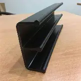
GSE PolyLock T HDPE termination strip Africa - the cast-in locking embedment profile for permanent geomembrane-to-concrete anchorage. Three T-anchors embed into fresh concrete; the exposed HDPE weld cap is extrusion-welded directly to the adjacent liner, creating a continuous, testable, leak-tight seal without metal battens, fasteners or sealants. Compatible with 1.0–3.0mm HDPE liners. 5m sections. Supplied and installed across Africa by Geosynthetics Africa.
Overview
GSE PolyLock T is the engineering standard for HDPE geomembrane termination into concrete structures - the detail specified when a liner system must transition from flexible geomembrane to a rigid concrete wall, plinth, sump, ring beam or headwall without creating a leak path.
Traditional metal batten systems penetrate the liner, depend on sealants at the waterproofing plane, introduce corrosion risk and create mechanical fastener penetrations that compromise containment continuity. PolyLock T eliminates every one of these failure modes. Three serrated HDPE T-anchors provide mechanical pull-out resistance in the concrete. The all-HDPE weld cap provides a clean, compatible fusion surface for extrusion welding directly to the geomembrane - the same weld that is QA/QC tested to ASTM D6392 and included in the project weld dossier.
Typical applications: heap leach sumps and plinths, TSF decant towers and headwalls, wastewater channels and weirs, process pond spillways, reservoir perimeter beams, landfill leachate chambers and any concrete interface in a lined containment system.
Installation: fixed to formwork or pressed into fresh concrete (minimum C20/25). Straight, angle, inner and outer corner joints formed on site using butt-welding at 220–250°C with a hot air welder and mirror adapter. After formwork removal, the HDPE cap is cleaned and extrusion-welded to the liner by a qualified welding technician. All welds tested and logged in the project QA dossier.
Note: PolyLock T is a cast-in system for new concrete only. For existing concrete, Geosynthetics Africa supplies stainless compression batten systems. PolyLock® is a registered trademark of Solmax. Distributed by Geosynthetics Africa under authorisation.
- MaterialHigh-Density Polyethylene (HDPE) - UV stabilised, carbon black
- StructureCast-in T-anchor embedment strip - 3 parallel T-anchors, HDPE weld cap
- ColourBlack
- StandardSolmax quality standard - GRI-GM13 liner compatible
- Roll Widthapprox. 140 mm wide · 22 mm T-anchor height
- Roll Length5 m sections (standard length)
Typical Properties
| Property | Test Method | Unit | Typical Value |
|---|---|---|---|
| Profile type | - | - | Cast-in T-anchor embedment strip - 3 parallel T-anchors |
| Material | - | - | HDPE black, UV stabilised - density ≥ 0.94 g/cm³ |
| Standard length | - | m | 5 |
| Profile width | - | mm | approx. 140 (148 ± 6) |
| T-anchor height | - | mm | approx. 22 |
| Compatible liner thickness | - | mm | 1.0 – 3.0 HDPE smooth and textured |
| Weld Method | - | - | Extrusion welding - hot air, mirror adapter, 220–250 °C |
| Minimum concrete grade | - | - | C20/25 — new concrete structures only |
Note: The above values are typical and not intended for specification purposes. Please refer to the product datasheet for full details.
Typical Applications
View all applicationsSecondary Containment & Bunds
Terminating HDPE lining into the concrete walls and floors of bund structures around tanks, fuel farms and chemical storage. The termination is the detail a compliance inspection examines first, because it's where a bund most commonly fails to hold. Cast-in profile gives a welded joint with no mechanical fixings to loosen.
Tank & Reservoir Linings
Lining concrete tanks, reservoirs and process water structures where the geomembrane must terminate watertight at the wall crest, floor junction or around penetrations. The T-anchor embedment holds under hydrostatic pressure trying to open the joint from behind.
Pump Stations & Sumps
Lining concrete sumps, wet wells and pump station chambers, where confined geometry means many internal corners and a high ratio of termination length to lined area. Inner and outer corner joints weld with T-straps to keep the profile continuous around the structure.
Mine Process Structures
Terminating chemically resistant lining into concrete launders, channels, plinths and containment structures in processing plants. HDPE throughout means the termination has the same chemical resistance as the liner, with no dissimilar material at the joint to become the weak point under process solution exposure.
Landfill & Leachate Structures
Lining leachate collection sumps, manholes, inspection chambers and concrete transfer structures within landfill systems. Provides a documented, welded termination at every concrete interface - the points where a lined cell most often leaks and where a regulator will look during inspection.
Compatible Systems
View all systemsStraight Joint
Profile-to-profile butt weld along a continuous run. Joint faces are cut square with a compass saw or metal cutting saw to give a clean, coplanar weld face. The standard condition on long tank walls and bund perimeters.
Angle Joint
Mitred butt weld where the termination line changes direction in plane. Faces are cut to suit the required angle before welding, so the profile follows the structure without a break in continuity.
Inner Corner Joint
Welded joint reinforced with a T-strap across the corner. Used at internal corners of tanks, bunds, sumps and pump stations, where the profile turns into the structure.
Outer Corner Joint
Welded joint with a T-strap on the external face. Used where the profile turns around an upstand, pilaster or projecting element.
Installation Guidance
Standard Method Statement
Jointing lengths - PolyLock-T is supplied in 5m lengths and butt-welded to form a continuous run. Cut joint faces square and clean using a compass saw or metal cutting saw, mitred to suit the angle where the termination line changes direction. Preheat a hot air welder fitted with a mirror adapter — a Leister Triac or similar, with a 250 × 250 welding mirror — to 220–250 °C. Hold both prepared faces coplanar against the mirror under slight pressure. When the material softens and bulges at the edges, press the faces together under high pressure for a maximum of 30 seconds. Inner and outer corners are welded with a T-strap across the joint. Extrusion welding the profile is possible, but a watertight connection to the concrete is only achieved when the T-bars are jointed to each other as well - welding the face alone leaves a continuous path along the anchors.
Vertical installation - For vertical faces, fix the welded profile to the formwork with nails at approximately 300mm centres, alternating sides. Nail length is selected to suit the shutter board thickness, typically 20–30mm. Check alignment along the full run before the pour, since the profile sets the line the geomembrane will terminate on and cannot be adjusted afterwards.
Horizontal installation - For horizontal surfaces, drill 4–5mm air vent holes along the profile at 1m centres, alternating sides. Press the profile into fresh concrete of minimum C20/25 grade under slight pressure and vibration, allowing trapped air to escape through the drilled holes. Venting matters: air trapped beneath the profile leaves voids around the T-anchors and compromises the embedment. Weight the profile down until the concrete has hardened.
After striking formwork - Once the formwork is struck, clean all concrete residue from the exposed profile face and remove every fixation nail. Both will prevent a sound weld. The geomembrane is then extrusion welded to the profile by a qualified welding technician. Cutting, welding and installation of the profile itself are carried out by the construction contractor on site; Geosynthetics Africa's crews execute the geomembrane-to-profile weld as part of the lining installation scope, with the joint included in the seam log and QA dossier.
Quality Assurance & Testing
Field QA/QC Checklist
- Delivery & Storage: Materials checked against the delivery note and conformance certificates, stored off the ground, covered from UV and kept clear of sharp objects and fuel.
- Formwork Fixing: Sheets fixed to formwork with anchor studs facing the concrete, joints aligned and no studs bent or damaged before the pour.
- Concrete Placement: Concrete placed and vibrated so studs are fully embedded without displacing or tearing the liner.
- Joint Welding: Joints between sheets and at construction joints closed with extrusion-welded strips after stripping the formwork.
- Weld Testing: 100% of welds tested by vacuum box (ASTM D5641) or spark testing, with repairs re-tested.
Manufacturing Standards
- Manufacturer QC certificates per roll
- Extrusion welds to manufacturer's installation guide
- ASTM D5641 vacuum box testing
- Spark (holiday) testing where specified
- Solmax quality standard - GRI-GM13 liner compatible
Documents
Product Selection Guide
Compare performance properties across the entire category hierarchy before specifying.
Installation & Method Statement
Standard deployment procedures, installation specifications, and field application method statements.
QA/QC Site Checklist
Field quality control procedures, inspection checklists, and testing standards to verify installation integrity.
Technical Data Sheet (TDS)
Guaranteed minimum average roll values (MARV) and material testing properties.
Chemical Resistance / Accessories Guide
Chemical compatibility matrix and list of auxiliary materials needed for installation.
Projects Using GSE PolyLock T HDPE Termination Strip
Submit your BOQ.
Get a quote – not just a price.
Upload your BOQ or speak to our technical team for expert recommendations and support.